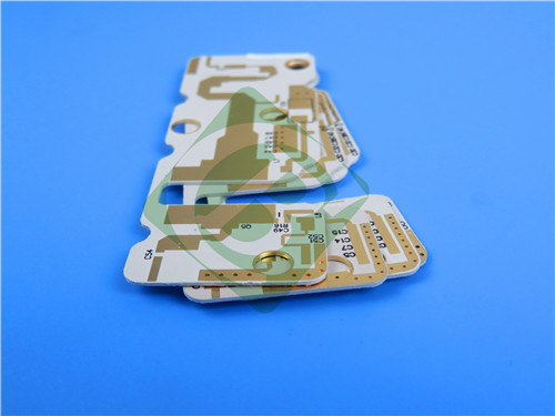
Rogers RO3006 2-Layer 5mil OSP PCB – High Frequency Microwave Applications
1. Introduction to Rogers RO3006 PCB
Rogers RO3006 laminates are ceramic-filled PTFE composites designed to offer exceptional electrical and mechanical stability, intended for use in commercial microwave and RF applications. The advanced circuit materials provide a stable dielectric constant (Dk) over a range of temperatures. This stability eliminates the step change in Dk that occurs for PTFE glass materials near room temperature.
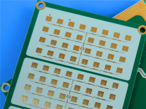
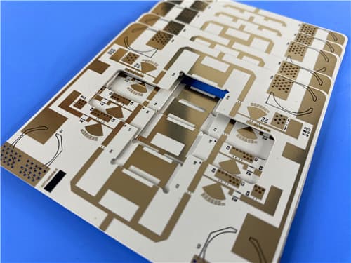
RO3006 laminates have a dielectric constant of 6.15±0.15 and dissipation factor of 0.002 at 10 GHz. This 2-layer rigid PCB is constructed entirely with RO3006 as the core material, making it ideal for automotive radar, GPS antennas, satellite communication, and patch antenna applications.
2. Key Features of Rogers RO3006 PCB
Dielectric Constant (Dk): 6.15 ± 0.15 at 10 GHz / 23°C Dissipation Factor: 0.002 at 10 GHz / 23°C Thermal Coefficient of Dk: -262 ppm/°C CTE (X/Y/Z): 17/17/24 ppm/°C (-55 to 288°C) Decomposition Temperature (Td): >500°C TGA Thermal Conductivity: 0.79 W/m/K Moisture Absorption: 0.02% Volume Resistivity: 10⁵ MΩ-cm (Condition A) Surface Resistivity: 10⁵ MΩ (Condition A) Copper Peel Strength: 7.1 lbs/in (1 oz EDC after solder float)
3. Benefits of Rogers RO3006 PCB
Uniform mechanical properties for a range of dielectric constants Ideal for multi-layer board designs with a range of dielectric constants Suitable for use with epoxy glass multi-layer board hybrid designs Low in-plane expansion coefficient (match to copper) allows for more reliable surface mounted assemblies Ideal for applications sensitive to temperature change Excellent dimensional stability (etch shrinkage <0.5 mils/inch) Volume manufacturing process – economical laminate pricing Exceptional plated through-hole reliability even in severe thermal environments
4. PCB Construction Details
| Item | Specification |
|---|
| Base material | Rogers RO3006 (ceramic-filled PTFE composite) |
| Layer count | 2-layer rigid |
| Board dimensions | 43.66mm x 28.01mm = 1 PCS, ±0.15mm |
| Minimum Trace/Space | 5/7 mils |
| Minimum Hole Size | 0.25mm |
| Blind vias | No |
| Finished board thickness | 0.25mm (5mil core) |
| Finished Cu weight | 1 oz (35 μm / 1.4 mils) outer layers |
| Via plating thickness | 20 μm |
| Surface finish | OSP |
| Top Silkscreen | Black |
| Bottom Silkscreen | No |
| Top Solder Mask | No |
| Bottom Solder Mask | No |
| 100% Electrical test | Used prior to shipment |
5. PCB Stackup (2-Layer Rigid Structure)
Copper_layer_1 (Top) – 35 μm (1 oz)
Rogers RO3006 – 5mil (0.127mm) dielectric core
Copper_layer_2 (Bottom) – 35 μm (1 oz)
Total thickness: 0.25mm (including copper layers)
6. PCB Statistics
Components: 20
Total Pads: 24
Thru Hole Pads: 13
Top SMT Pads: 11
Bottom SMT Pads: 0
Vias: 34
Nets: 2
7. Rogers RO3006 Material – Product Introduction
RO3000 high frequency circuit materials are ceramic-filled PTFE composites intended for use in commercial microwave and RF applications. This family of products was designed to offer exceptional electrical and mechanical stability at competitive prices. RO3000 series laminates are ceramic-filled PTFE based circuit materials with mechanical properties that are consistent regardless of the dielectric constant selected. This allows the designer to develop multilayer board designs that use different dielectric constant materials for individual layers, without encountering warpage or reliability problems.
RO3000 materials exhibit a coefficient of thermal expansion (CTE) in the X and Y axis of 17 ppm/°C. This expansion coefficient is matched to that of copper, which allows the material to exhibit excellent dimensional stability, with typical etch shrinkage (after etch and bake) of less than 0.5 mils per inch. The Z-axis CTE is 24 ppm/°C, which provides exceptional plated through-hole reliability, even in severe thermal environments.
8. Features and Benefits Summary
| Feature | Benefit |
|---|
| Dk 6.15 ± 0.15 @ 10 GHz | Exceptional uniformity and tight tolerance for consistent impedance |
| Df 0.002 @ 10 GHz | Low loss for high-frequency microwave designs |
| Thermal coefficient of Dk: -262 ppm/°C | Stable electrical performance over temperature |
| CTE matched to copper (17/17/24 ppm/°C) | High reliability plated through holes, excellent dimensional stability |
| Thermal conductivity 0.79 W/m/K | Efficient heat removal |
| Moisture absorption 0.02% | Minimal impact on electrical properties in humid environments |
| Volume & surface resistivity 10⁵ | Good insulation properties |
| Volume manufacturing process | Economical laminate pricing |
9. RO3006 Typical Properties (Data Sheet)
| Property | Typical Value | Direction | Units | Condition | Test Method |
|---|
| Electrical Properties |
| Dielectric Constant (process) | 6.15 ± 0.15 | Z | — | 10 GHz / 23°C | IPC-TM-650 2.5.5.5 |
| Dielectric Constant (design) | 6.50 | — | — | 8 GHz - 40 GHz | Differential Phase Length Method |
| Dissipation Factor | 0.0020 | Z | — | 10 GHz / 23°C | IPC-TM-650 2.5.5.5 |
| Thermal Coefficient of Dk | -262 | — | ppm/°C | -50 to 150°C | IPC-TM-650 2.5.5.5 |
| Volume Resistivity | 10⁵ | — | MΩ-cm | Condition A | IPC-TM-650 2.5.17.1 |
| Surface Resistivity | 10⁵ | — | MΩ | Condition A | IPC-TM-650 2.5.17.1 |
| Thermal Properties |
| Decomposition Temperature (Td) | 500 | — | °C TGA | — | ASTM D3850 |
| CTE (X-axis) | 17 | X | ppm/°C | -55 to 288°C | IPC-TM-650 2.4.41 |
| CTE (Y-axis) | 17 | Y | ppm/°C | -55 to 288°C | IPC-TM-650 2.4.41 |
| CTE (Z-axis) | 24 | Z | ppm/°C | -55 to 288°C | IPC-TM-650 2.4.41 |
| Thermal Conductivity | 0.79 | Z | W/m/K | 50°C | ASTM D5470 |
| Mechanical & Physical Properties |
| Copper Peel Strength | 7.1 | — | lbs/in | 1 oz EDC after solder float | IPC-TM-650 2.4.8 |
| Young's Modulus | 1498 / 1293 | — | MPa | 23°C | ASTM D638 |
| Dimensional Stability (MD, CMD) | -0.27 / -0.15 | — | mm/m | Condition A | IPC-TM-650 2.2.4 |
| Moisture Absorption | 0.02 | — | % | D48/50 | IPC-TM-650 2.6.2.1 |
| Density | 2.6 | — | g/cm³ | 23°C | ASTM D792 |
| Specific Heat Capacity | 0.86 | — | J/g/K | — | Calculated |
| Lead-Free Process Compatible | Yes | — | — | — | — |
10. Primary Application Areas
Automotive radar applications Global positioning satellite antennas Cellular telecommunications systems – power amplifiers and antennas Patch antenna for wireless communications Direct broadcast satellites Datalink on cable systems Remote meter readers Power backplanes
11. Quality Assurance
Type of artwork supplied: Gerber RS-274-X Accepted standard: IPC-Class-2 Availability: Worldwide 100% Electrical test prior to shipment
12. Standard Thicknesses, Panel Sizes & Claddings
| Parameter | Options |
|---|
| Standard Thicknesses | 0.005" (0.13mm) ±0.0005", 0.010" (0.25mm) ±0.0007", 0.025" (0.64mm) ±0.0010", 0.050" (1.28mm) ±0.0020" |
| Standard Panel Sizes | 12" x 18" (305 x 457mm), 24" x 18" (610 x 457mm), additional sizes available |
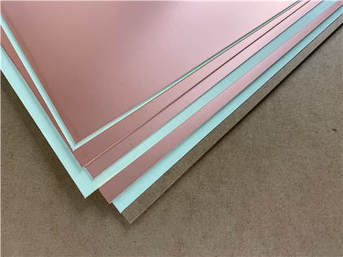
| Standard Claddings | Electrodeposited Copper: ½ oz (18μm), 1 oz (35μm); additional claddings available |
|